Determining what mode struts are in manually
This post provides a description of a simple set of tests that you can perform on your struts to tell what mode they are operating in.
There's various reasons why you might want to do this:
-If your ECS system has failed and your getting blinking lights or your getting no lights at all
-Or you've disconnected your ECS system altogether but have the ECS struts still mounted and not sure what state they were left in.
-Or you've decided to mount ECS struts in your Non-ECS equiped 3/S so you can use aftermarket lowering springs and you've bought somebody elses used struts and want to know what mode their in.
Note: many comments have been made before that if the ECS system has failed it will automatically put the system in "sport" mode. This is true only if (a) the ECS module is functioning correctly & (b) if all the struts are operational. Many times this is not the case.
What you need for the test:
- A multi-meter: set to continuity test mode.
- A set of alligator test clip leads
- access to the tops of your ecs struts.
Procedure for the test
----------------------
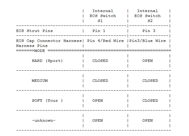
The procedure basically tests to see what state the internal Switches (S1 & S2) of each strut are in. i.e. are they open or closed. The state of the switches together corresponds to which dampening mode the ECS strut is configured for.
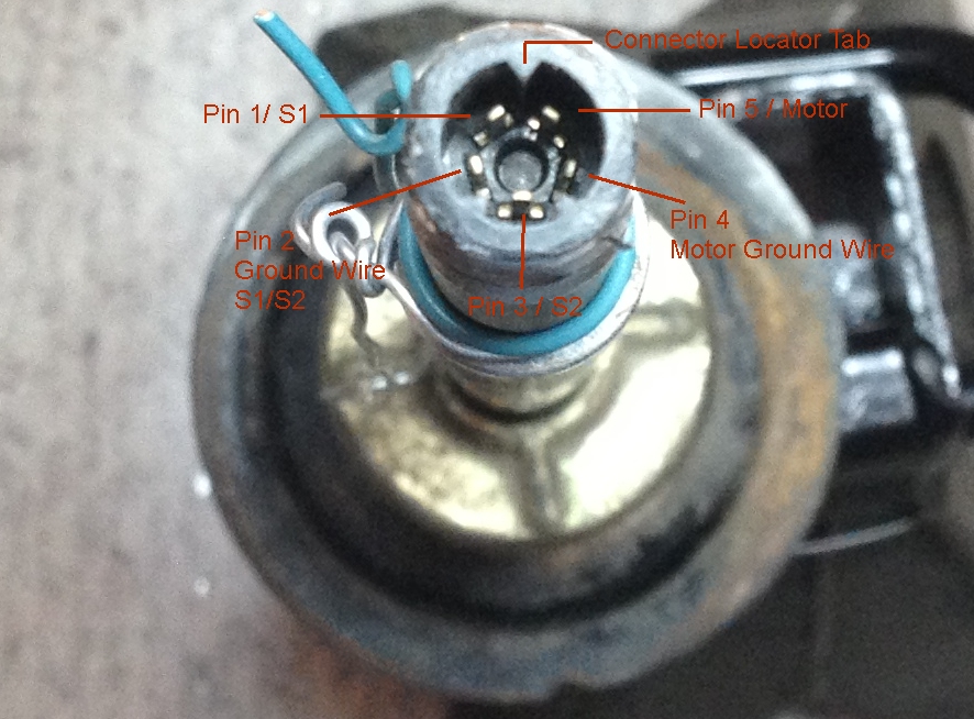
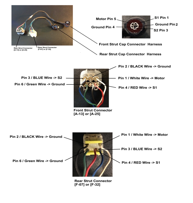
(1) You can either test the pins directly on the top of the strut OR you can test the pins of the cap-connector harness that connects to the top of the strut.
The latter is somewhat easier since it's easier to get at the pins - but you need a good working cap harness.
CAUTION: If you test the pins directly on top of the strut take care not to bend or break them.
The instructions below show using both methods.
(2) Connect one end of the multimeter to the Ground wire of the strut that is used by the internal strut switches. You will be testing for continuity between this ground pin & the other two S1 & S2 pins.
NOTE: The ground wire of the strut used by the internal switches is Pin 2 directly on the strut or Pin 6/Green wire of the connector Harness
(3) Connect the other end of the multimeter test probe to the S1 (Switch 1) of the strut and write down whether it is an Open connection or a Closed connection relative to the ground pin.
Note: S1 is Pin 1 directly on the strut or Pin 4/Red Wire of the connector harness.
(4) Now repeat (3) except Connect the end of the multimeter test probe to the S2 (Switch 2) of the strut and write down whether it is an Open connection or a Closed connection to the ground pin. Same ground pin is used.
Note S2 is Pin 3 directly on the strut or Pin 3/Blue Wire of the connector harness.
Now based on your readings for S1/S2 look in the table below and you will be able see the what mode the strut is in.
For example if your readings showed that S1=Closed & S2=Open then your strut is in Hard Mode.